We were the guests on CBC Radio One’s Cinq à Six on Saturday March 26th talking about analogue production and some music recorded at The Bottle Garden. Jeanette Kelly was a great and affable host. And it turns out she has ace razor-blade editing skills from her early days in radio production.
We built a pair of PRR 176 stereo vari-mu compressors a couple years ago and we really love them. They’re maybe a little quirkier and less predicable than 1176 rev D FET limiters or LA2As, but on the whole they’re probably our favourite compressors–especially for vocals and clean guitars. They’re also very capable on stereo bus duty. Boards are no longer available for sale but un-built PCBs are frequently listed on the GroupDIY Black Market. We recently did a few modifications to our PRR 176s so I thought I’d do a writeup.
µ Oughta Know
Vari-mu, variable µ, or ‘tube’ compression is one of the major dynamic range compression circuit categories, the other main types being: Optical (LA2A); Diode Bridge (EMI TG12413, Neve 2254); FET (UREI 1176, early Allison Gain Brain); Pulse Width Modulation (Pye); and VCA (dbx 160, SSL, later Valley Gain Brain, most modern compressors). Each approach (and each circuit implementation) imparts its own sound though differing time constants, non-linearities and distortion products that are sometimes quite euphonic.
Prior to the invention of compression, dynamics were either controlled by manually adjusting levels or by performers positioning themselves nearer to or farther from the mic. Difficulties might arise with unpredictable talent: One thinks of the MGM crew charged with capturing the lion’s roar. Similarly, early Elvis Presley sessions allegedly employed an assistant to grab the King by his shoulders and physically vary his distance to and from the microphone based on musical dynamics. (Other reports say Elvis’s voice went through an RCA vari-mu compressor set to a gentle 2:1 ratio).
I believe vari-mu was the earliest electronic automatic gain control technology. Data are sketchy but as far as I can find, the Western Electric 110 compressor from 1937 is the first such unit. You can read a circuit description on page 563 of the December 1937 issue of Wireless World. Some say the Langevin Progar was developed earlier but took longer to come to market. Click here for a rough timeline of compressor development.
Unfettered Progress
The induction of the 1176 FET compressor in 1967 sounded the death knell for variable µ compression development. FETs are capable of faster attack times (which was crucial for the broadcast clients looking to get the loudest possible signal without over-modulating). The slower, more transparent optical compression technology cöexisted with vari-mu since the 1950s, but the new FET types (and the roughly contemporary diode bridge type) seemingly bested the old tube-based units in every important way: faster, quieter, wider control range, more reliable, and of course cheaper build costs. Thus development of new vari-mu types ground to a halt by the late 1960s.
Actual working engineers never quite gave up on tube compression. John Fry of Ardent studios called the Universal Audio 176 his compressor of choice for Radio City. And the Fairchild 670’s reputation grew to where it was probably the most coveted outboard gear unit in the world (last time I checked, they were going for $45K USD) .
Manley released their stereo Variable Mu compressor in 1994 (which I think was the first new major production tube compressor since they fell out of favour in the late-60s/early 70s). A few years later the Thermionic Culture Phoenix (supposedly based on the EMI-modified Altec 436) came out. Both of these units were very nice-sounding but neither differed much from vintage designs (not necessarily a bad thing but it made them very expensive).
Then in 2003, a guy who goes by PRR (don’t know his full name or background–I gather that he’s a professor of some sort) conceived a cheap-to-build modern vari-mu and gave his schematic and circuit description away for free. PRR’s design was a novel approach emphasizing the use of cheap, easily obtainable components (like ubiquitous 12AU7 tubes for gain reduction). As far as I can tell, his was the first to dispense with a vacuum tube side chain signal. Interestingly, Rein Narma, the Fairchild 660/670 designer, says in this interview that he’d have used a solid state side-chain if it was available to him.
Abe Chapman of AC Sound Studios came up with his circuit boards as a sort of cross between the PRR Vari-Mu compressor design and elements of the classic Universal Audio 175/176, such as employing a 6BC8 tube for gain reduction. Plus he added a few modern refinements, like: stereo or dual mono operation, bypass, and a switchable side-chain hi-pass filter (to reduce pumping when used on a stereo bus).
We didn’t tally the costs of building these compressors, but I’m quite sure it was under $2000 for all four channels. The priciest components were the audio transformers. Enclosures were probably the next most expensive items. We used budget, powder-coated steel 2RU cases with aluminum front panels. Working with steel is pure torture so I’d highly recommend getting an all-aluminum chassis if you can afford it.
Rev 1 Build Notes
Abe’s first circuit board for the PRR 176 was already pretty well worked out. The only major problem was that the power supply on the main board would add noise to the circuit. The relatively easy work-around was building a simple Veroboard circuit for power supply rectification and filtering.
Rev 1 off-board power filtering mod
The circuit also lacked a bypass. This was relatively easy fix by lifting one leg of the side-chain capacitor and installing a front panel switch. Because this capacitor is in parallel with the side-chain high-pass filter cap, you need to engage the HPF switch for bypass to work. It’s a bit inelegant but it works. Note that this is a compression bypass, not a hard bypass. Hard bypass requires extra circuitry and relays. The advantage to this ‘soft-bypass’ approach is that you can use it as a line amplifier (e.g. extra clean gain after a mic preamp). The disadvantage is that you can’t do quick A-B comparisons between compressors.
Rev 1 soft bypass mod
For the Rev 1 we used Swedish Lundahl transformers for input; UK-made BBC/Sowter units for interstage (a really critical component for this compressor); and Canadian Hammond 1:1 600 ohm transformers for output. We initially used the optional IC balanced output but after some testing we decided we preferred the transformer outputs.
Lundhal LL1540 Transformer
Sowter BBC type 4257 Transformer
Hammond output transformer
Everything worked quite well from the start except for the odd incident of thermal shutdown. We discovered that the tube filament regulator’s heat sink was inadequate. The fix was simple: mount the regulator IC to the case.
Rev 2 Build Notes
PRR 176 Vari-Mu Rev 2
The Rev 2 PCB set provided a separate board for its power supply. Again everything went well right off the bat except for the tube filament regulator getting too hot (again, mounting it to the case fixed the problem).
For this unit, we used less expensive American-made Edcor input transfers, Lundahls for the interstage, and again Hammonds for the output. This transformer array gives a subtly different sound.
We socketed the capacitors for the side-chain high-pass filter in order to experiment with different values. We ended up liking Abe’s default choices (tho an extreme hi-pass made for an interesting de-esser effect).
Side-chain HPF capacitors
Like the 176 and 1176, this compressor uses the input signal to set the compression threshold. We decided to do a simple modification to make this a bit easier to use in the real world. We fitted multi-turn trimmers to a switch and mounted them to the front panel and then ran the switch to the circuit board. This gives us a quick, calibrated high or low threshold (I’ve always found the 1176’s threshold impractically high for typical console ‘send’ levels). With stereo linking engaged, the circuit uses the channel 1 attack and release controls for both channels (input and output levels must be carefully matched for each side).
PRR 176 switchable threshold
Calibration etc
The calibration procedure is pretty straightforward. Here’s Abe’s description:
Trimmers:
1k VR3, VR9 ….this balances the power between the 2 halves of the 6BC8 tube. Helps if you don’t have a perfectly balanced tube.
100R VR1,VR4 adjust for minimum “thump”
1k VR5, VR2 Control Meters, Power on, let it warm up for a bit (10 minutes or so) turn until meters read “0” gr.
There are a couple different ways to do the ‘thump’ calibration (which is, by far, the most crucial). The simple way is to feed a 20hz clean sine wave, dial in a decent amount of gain reduction and adjust for the least distorted waveform on an oscilloscope. A slightly more sophisticated approach is to feed the compressor gated bursts of high frequency (20KHz is good) and adjust for minimum thump. Here’s a good overview of both approaches.
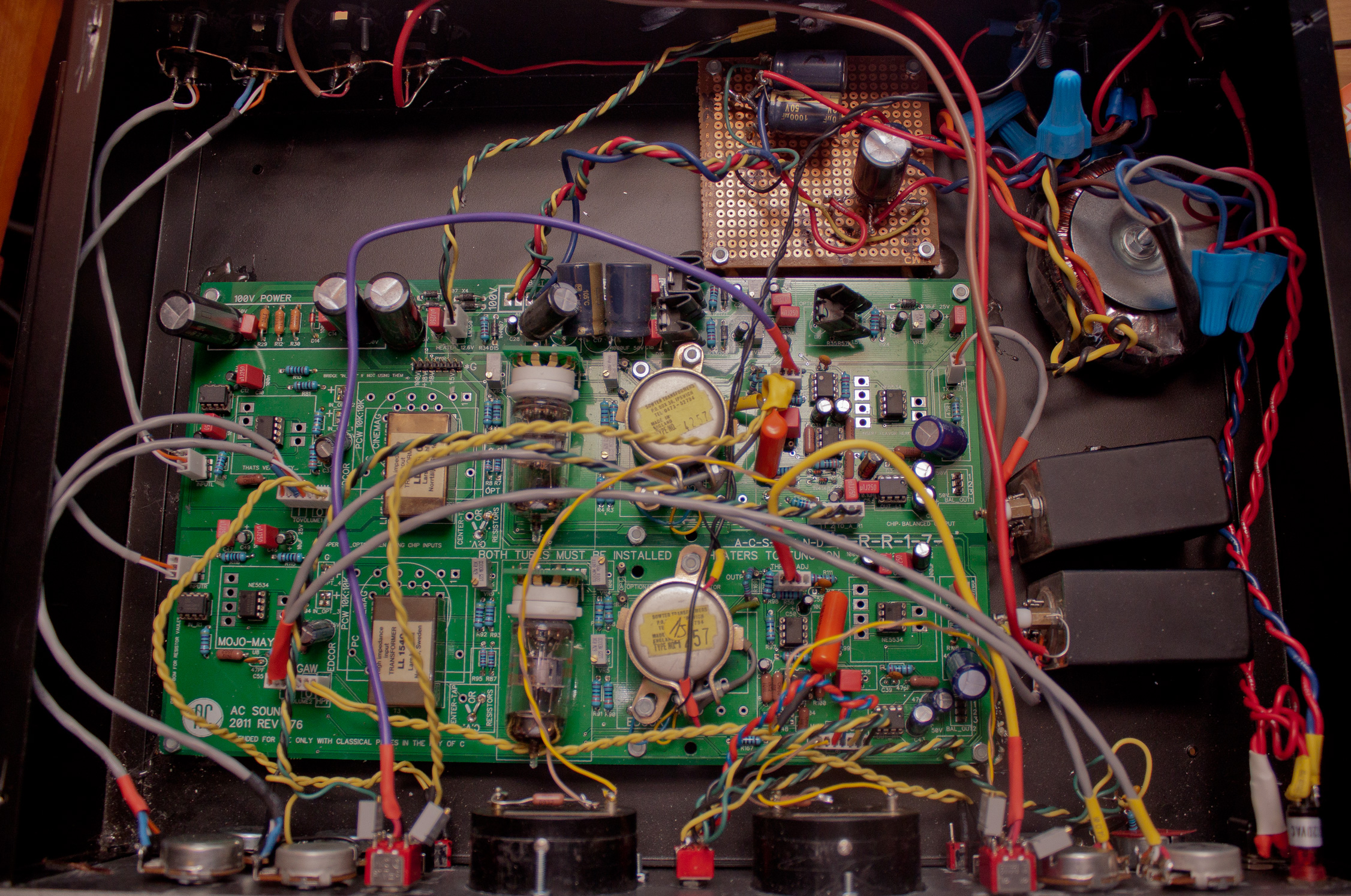
We did encounter a several 6BC8 tubes had to be rejected because they weren’t balanced well enough to work in the circuit (so it’s wise to factor in the cost of buying some extra tubes). As you can see by the photos, we’re no experts at wire dressing but the compressor is very quiet and we’ve had no problems with oscillation despite the extra all the extra wiring from our modifications.
American RCA 6BC8
Canadian RCA 6BC8
On our Rev 1, the meter calibration wouldn’t quite go to zero with our NOS Weston meters (found at Leeds Radio in New York).
Weston type 506 1mA meter
The simple solution was to add a 1Kohm resistor in series.
Weston Meter zero set mod resistor
We tried to measure the attack and release times with software but didn’t have much luck. The compression ‘knee’ is quite soft so it’s difficult to say when you’d deem it to be ‘in gain reduction’. It looks like it’s a bit faster than the 176’s 100 µsec attack time (but noticeably slower than the 1176’s 20µsec maximum) but I’d need to research measurement standards to know for sure. The settings aren’t fool-proof: even when well-calibrated, it’s possible to get some ‘thumping’ noise if the very fastest attack and release times are used on bass heavy material.
The front-panel finish was done with Tremclad ‘hammered finish’ spray-paint (a terrible product with noxious fumes and lumpy, inconsistent coverage properties) and the lettering done with old Decadry transfer sheets (an unbearably tedious job) and protected with clear nail lacquer (we tried two brands: ‘OPI Start to Finish’ which sucks and almost destroyed the already sketchy paint job; the other type called ‘Mavala top coat’ worked OK). If you hate metalwork as much as I do, circular Neutrik Powercon connectors are a small mercy to save yourself the agony of drilling a rectangle for a standard IEC inlet. Amateur metalwork generally involves breathing in nasty particulate matter, countless splinters, and hours of filing. If you can afford it you’d be best off getting Front Panel Express or a local engraver to finish your chassis.
Neutrik PowerCon connector: Mercifully easy to drill.
Further reading
See the original build threads for much more information (including schematics, bills of materials, wiring guides, etc.)
I recently made a Super 8 video with my friends in the band Sheer Agony and I thought I’d share some info on what it’s like working with small format film on the lowest possible budget. I directed it (with Caitlin’s help) but the band contributed many of the ideas. It’s about a crooked police officer (singer/guitarist Jackson MacIntosh). During his collection rounds he stumbles upon a loft show where he suddenly, unexpectedly, must confront his deeply-repressed dream. It’s all pretty lite fare but we did spend a bit of time researching police message boards to try to get inside the law enforcement mind.
Here’s the video:
The album it’s taken from, Masterpiece, is superb. It’ll be out on October 30th. Read about it here.
Some earlier Super 8 videos that Caitlin and I made for our own band are viewable here. I made many, many (sometimes expensive) mistakes in the course of making these that hopefully you won’t need to repeat.
Can you even get film?
First off, yes, Super 8 film is still available new. Kodak sells four different stocks as I write this. Adox also makes a b&w reversal (projectable) stock. Another b&w stock is available from the Czech company Foma. Wittner Cinetek sells a number of (expensive) specialty stocks. Ferrania in Italy is close to releasing a new colour reversal super 8 film.
And yes, you can still get the film developed and scanned quite easily. We use Niagara Custom Lab and Frame Discreet in Toronto.
Used cameras are abundant and there’s even a new Super 8 camera currently in production: The highly advanced (and $$$) Logmar. Using a garbage camera (like this Bentley piece of crap) is a false economy. I’ve mostly used Canon and Nizo cameras but other good names include Beaulieu (they have a dual rep: excellent optics but extreme fragility); Elmo (they also make the best projectors); Nikon (especially the R10); Eumig, and Leicina. Soviet-made Zenit Quarz cameras like model 1x8S-2 have a pretty good rep too.
Film and processing are pricier than in the past (you could once buy and develop carts at your local drug store) but I’d still say it’s the best time ever for making a music video (as opposed to a home movie) on Super 8. High quality Super 8 scans are fairly recent development; film, even 8mm, holds a lot of information. Older telecines looked very flat and blotchy (unless you did a 16mm blow-up) and didn’t come close to capturing the quality detail that was evident when projecting reversal 8mm film.
A few considerations
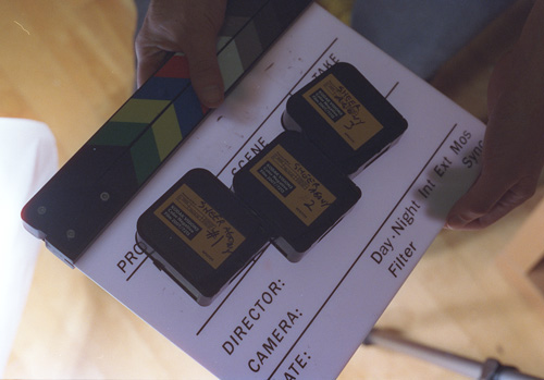
Shooting Ratio (the ratio of footage shot to footage used): for this Sheer Agony video we only had three 50′ cartridges of film. This gave us a little under 10 minutes of footage (including the titles, which were filmed). The video’s runtime was 2 minutes and 16 seconds. I’ve read that a 10:1 is considered pretty normal for film productions and 6:1 is considered economical. Ours was closer to 4:1 which definitely left very little to chance (a higher ratio would’ve let us do alternative takes with riskier-but-cooler lighting). But if you’re really determined to do things on the cheap, a 1:1 ratio ‘1-take super 8’ is do-able. Keep in mind that dumb technical mistakes happen (see image below) and people laugh (plan on tripling your required shooting ratio if you work with giddy people).
A shot from an earlier video ruined because I didn’t notice my own shadow.
There’s seldom enough light: when working outdoors be mindful of the fact your lighting conditions are constantly changing. This is doubly true as it approaches dusk. If you need to shoot at dusk, be prepared to hustle before you run out of light. The fastest (most light sensitive) Super 8 film is Vision 3 500T (rated at ISO 500 in tungsten light; ISO 320 in daylight with an 85 filter*); Generally speaking, the higher the ISO, the grainier the film. If you’re certain you’ll be working under very bright sunlight (or if you’ll have extremely bright movie lights) Vision 3 50D is so fine-grained it can almost look like 16mm.
Shutter Angle: Super 8 cameras with an “XL” usually have a larger shutter angle (maybe 220º or so) vs the traditional angle of around 150º. The larger shutter angle will allow filming in lower light. On the other hand, a smaller angle will produce a somewhat sharper image and less motion blur at a given frame rate. Some high-end cameras allow you to switch the shutter angle.
*Every Super 8 camera has a built-in 85 filter designed to colour correct tungsten film used in daylight (otherwise the footage will have a blueish tinge). Usually a sun symbol indicates the filter is switched on and a lightbulb means ‘off’. Some recommend using a screw-on 85 lens filter since the built-in one may be a bit dusty or faded but I’ve personally never had a shot ruined with the internal filter of any of my cameras. If you get your Camera serviced, ask the tech to check the status of your filter.
Depth of field (DOF): A Super 8 camera’s viewfinder does not simulate the actual depth of field (ie the range from near to far where objects appear reasonably sharp). The subject distance, lens focal length, f-stop, and film format all affect DOF. In the worst case, like if you’re zoomed in and the light is low, it’s quite possible to have a DOF of only a few centimetres. That means almost an entire scene could be out-of-focus even if it looked perfectly fine through the lens. Understanding depth of field helps you know how much light you need (probably more than you think) and helps you accurately frame your shots in three dimensions. If you have an iPhone or Android, Kodak’s free Cinema Tools app has a nice Depth of Field calculator.
Focussing: it’s very easy to ruin all your footage if a camera’s diopter is set incorrectly. The diopter adjustment sets the camera’s optics to match your own eyesight. The typical technique is to focus the camera on a bright distant object with the lens set to infinity (∞). Alternatively, you can double-check your focussing by comparing to the meter/feet marking on the lens and then measuring from the film plane mark (Φ) to the object in focus. If two people with differing eyesight are going to be shooting it’s best to get a second camera (the cameras are cheap, film isn’t).
Know your camera’s equivalent shutter speed: this figure varies from camera to camera and based on the filming speed (18 frames per second and 24fps are the most common). For example, my Nizo has the equivalent shutter speed of 1/43 sec @ 18fps (1/40 would be close enough for rock & roll) and 1/57 sec @ 24fps. You need this info if you want to use an external light meter.
Consider using a tripod: Super 8 is inherently a bit jittery (because there’s no pressure plate over the film gate–the new Logmar camera is the exception) so even with a fairly steady hand, the cumulative shake can be be quite high. Also, cameras are more sensitive to motion blur at the telephoto end of the lens; wide angle is a bit more forgiving if you need to do hand-held shots.
Lipsync: very few Super 8 cameras have crystal sync motors so the speed is going to drift a little bit. This usually isn’t noticeable but it can make it difficult to get lipsync to line up. If you have enough time, it’s a good idea to break your sync’d bits up into smaller chunks.
Bring a toothbrush: it’s a really good idea to clean the film gate every time you change cartridges. Accumulated dirt in the film gate scratch the film or create large blotches in the picture.
Student and Co-op discounts: You can get sizeable discounts on film stock, developing and scanning if you’re either a student or a member of a film co-op.
Equipment Used for the Video
Cameras: For this video we used a Canon AutoZoom 814 (Japan 1967) and Nizo S80 (West Germany 1969). The former was a hand-me-down and the latter a cheap garage sale find. Both camera required servicing to both their lenses and electronics to function correctly. Jean-Louis Séguin, a recently retired Concordia University Communication tech did the work. He’s amazing.
Lighting: We only had a pair of Arri 600w tungsten open face lights with stands, various gels and soft boxes. We rented them from Main Film. We didn’t have dimmers (they would have been really handy). If you really wanted to cheap out, these 450w equivalent CFL bulbs put out a decent amount of light (we’ve used them in the past).
The two lights we rented
Light metering: A Sekonic L-398 (this is a really basic meter that doesn’t require batteries and is pretty easy to find used). Even though both cameras have internal light meters and can read the notches for Vision 3 200T (most super 8 cameras’ internal meters will only read 25/40 and 100/160 ASA* [daylight/tungsten]) I prefer to use an external meter. I’ll often want an off-centre spot to be the lighting reference and in cases where the lighting changes in a shot (eg a pan) you won’t get an annoying glitches from the camera’s iris adjusting. Also, many cameras require very expensive substitutes (like the $$$-but-quick-draining WeinCell) for the now-banned PX625 mercury cell for their internal light meter. Negative film (like the colour Vision 3 series) has much more exposure latitude (ie it’s more forgiving if you screw up) than reversal (projectable) film like Tri-X.
*ASA and ISO are identical units for film speed.
Film: We were limited to three carts of Kodak Vision 3 200T (tungsten balanced) colour negative film. We shot at 18fps. 24fps offers smoother motion but requires more light and is less economical (natch). And as mentioned, the film was developed at Niagara Custom Lab and scanned to HD video at Frame Discreet (who also did basic colour grading).
Props: We rented the cop uniform at a nearby shop called Malabar. Most of the other stuff was scrounged up by the band members and me. The unusual photo was found inside a used reel of analog tape.
Eerie photo found inside a used analog tape reel
Editing: We used Adobe Premiere CS5. We mostly did straight cuts so any non-linear editor would’ve worked fine.
Grain reduction: I think Super 8 film grain looks great. Unfortunately, neither YouTube nor Vimeo can handle much film grain. The inherent randomness of grain confuses the compression schemes leading to blotchy digital glitch artefacts. That is why I feel that using the noise reduction plugin Neat Video is a necessary evil. The trick is using the only the tiniest amount of reduction. José Luis Villar’s advice here is excellent.
If you don’t need to upload the video to the internet, (like for a private showing) you probably don’t need to use grain reduction.
Spanish fashion photographer José Luis Villar makes the most technically adept Super 8 clips I’ve seen. He’s also been extremely generous to us about sharing his knowledge. Here’s his site.
Super8data and Super8wiki both have exhaustive collections of photos, specifications and manuals for cameras and other gear.
Niagara Custom Lab does film developing and also sells film stock. They’re located in Toronto.
Frame Discreet does very high-quality film scanning and colour grading. They’re also in Toronto. Since we’ve done this video, they’ve upgraded their rig to a 5k Lasergraphics ScanStation.
Main Film is our local film co-op. We get a discount on film stock and development as members. They have a nice collection of equipment for rent too.
Vision Globale/Mels is the Montreal distributor for Kodak cinema film. Alban Berg was film person last time I was there (totally nice, helpful guy).
Logmar of Denmark make the world’s most advanced Super 8 camera. It’s pricy but its footage approaches 70s 16mm film in quality.
Jean-Louis Séguin is an excellent (and affordable) Montreal-based cinema camera tech. Contact us if you need his email (no flakes plz).
35mm set photos
We had a still camera floating around loaded with Cinestill film (which is repackaged Kodak cinema film) pictures were taken by the band, Caitlin, and me. Kinda (but not really) gives the idea of what it might have looked like shot on 35mm.
Homeshake’s Peter Sagar as the seen-it-all bartender
Early this year we scrounged together the cash to get the parts to build a D-LA2A, a very clever and well-documented project where you can make a pair of LA2As on a single printed circuit board.
The LA2A, if you’ve never encountered one, is a circa-1965 compressor or levelling amplifier. It’s one of those classic pieces that never really fell out of favour in pro audio circles. It only has two knobs (gain and peak reduction) and it’s pretty much impossible to get a bad sound out of it.
If you’re not familiar with audio compressors, they’re basically devices designed to lessen the differences between loud and soft audio signals, smoothing out erratic dynamic shifts. The LA2A’s is historically significant because it was the first truly effective ‘optical’ compressor, meaning it controls gain through electroluminescence and photo-resistance. As the audio signal intensifies, an electroluminescent panel glows; this in turn causes a coupled photo-resistive circuit to trigger gain reduction.
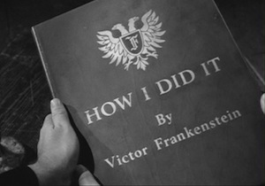
My description is horribly crude, so I scanned these pages from the Audio Cyclopedia by Howard Tremaine, which explains the LA2a’s workings clearly and accurately (click them to enlarge); for LA2A aficionados like us, discovering this document evokes Young Frankenstein:
The LA2A as explained by smart people
Audio Cyclopedia LA2A part 1
Audio Cyclopedia LA2A part 2
Audio Cyclopedia LA2A part 3
For the truly curious, a person named Christian Sugar created this very nice circuit deconstruction:
Christian Sugar’s LA2A circuit deconstruction
Twin peak reduction: the making of a sequel
We’d already built a single LA2A clone in a 3RU chassis using a Drip Electronics PCB a year earlier, and we’ve used it on pretty much every session since. When we read about the DLA2A we were pretty impressed that that Volker, the German fellow who designed the circuit board, was able to squeeze the two of these comps onto a single compact board without compromising anything. And as a bonus, LA2As work quite well stereo-linked as bus compressors.
The [Silent:Arts] D-LA2A printed circuit board
We decided to go for it and ordered everything so they’d arrive in time for the Christmas holidays. The Printed circuit board and a custom toroidal power transformer came from the guy in Germany who thought the whole thing up [Silent:Arts] (he’s a classy fellow, the package only took about a week to ship from overseas and he tossed in some gummy bears); we got the audio transformers from Edcor in USA (which are much cheaper than the British Sowter transformers we used for the Drip LA2a); the tubes were from thetubestore.com in Hamilton; we found a Par-Metal aluminum chassis on eBay; we got stereo-matched T4B opto-attenuator units from Drip in Santa Fe; the rest of the parts were either from a local surplus shop or Mouser Electronics in Texas (we’re kinda glossing over this: prepare for hours of staring at catalog pages on computer screen to order all the resistors, capacitors and other bits and bobs—it’s the second most annoying part of all this DIY electronics stuff, next to only the dreaded metalwork).
The first sines of trouble or Doctor, it hertz when I do this
The build was quick and straightforward. It only took a day-or-so (except for the metalwork–that was annoying and tedious and we have no real aptitude for it) and everything worked from the first power up. There was only one bug–at very high gain levels it would self-oscillate. Even though it didn’t interfere with normal usage (it would only oscillate at impractically high levels) this still really stuck in our craws. We needed to do something about it.
To begin troubleshooting, we checked it out with the ‘scope. As the pic below shows, it was pretty clean sine wave at 30Khz. Lacking much in the way of repair know-how, this didn’t really tell us anything that we could act upon. It did, however, allow us to take a picture of a nice ‘m’ shape.
At higher gain settings, our D-LA2A was oscillating at about 30kHz.
In keeping with our astoundingly foolish troubleshooting ways, we decided to change a bunch of things at the same time. This assured us that even if we set things right, we’d never know for sure exactly what fixed it.
The first thing we did was add a socket to C4, the capacitor that governs the high frequency response. This let us choose the precise cap value to get us a flat response up to 20KHz without allowing too much ultrasonic (>20KHz) signal to pass through (which could contribute to that oscillation). It turned out that we had to use different values for the two channels to get them to match exactly (100pF and 250pF).
We decided to add a socket for C104/C204 (C4 in the original LA2A schematic). This capacitor plays a large part in determining the frequency response.
Next, we completely re-wired the whole thing. Lead dressing is a black art to us. We had the leads fairly long intially so that we could run them far away from any hum-inducing parts. With the re-wiring, we decided to go the route of keeping the wire lengths as short as possible (our theory being, there’s less surface area for interference to creep in). Once again, thanks to our lunkheaded and impatient try-a-bunch-of-things-at-the-same-time troubleshooting ways, we’ll never know 100% for sure if this made any difference. It did at least seem to lower the noise floor a bit.
Along the same lines, we also set about rearranging the audio transformers. Previously, they were tidily and symmetrically laid out. We changed them so they’re as far away from each other as we could fit. We used bolts stuck to the chassis with JB Weld for mounting. (Aside: JB Weld is good stuff–Freelove Fenner would totally be up for writing a jingle for the company. If you’re reading this JB Weld person, let’s talk turkey).
Another minor change we made was to remove the neon bulbs that are used for regulating the gain reduction metering and replace them with zener diodes. The zeners are allegedly quieter and more stable.
Here’s the innards of our D-LA2A. They had been a little bit tidier before but we shortened nearly all the leads in the course of troubleshooting the oscillation issue; the veroboard in the back is just there because we accidentally bought PCB mount pots for the zero set.
The last major change we made was modifying the circuit to use 12AY7 tubes rather than 12AX7s in the V1 position. This lowered the maximum gain slightly, but the AY7s are nicer sounding (subjectively, natch) and less trouble-prone tubes. This required a few resistor changes in the circuit. This was all first suggested by a knowledgeable fellow named CJ in California.
The good news is that all these changes (or one of these changes−who knows?) worked! Our D-LA2A is now quieter and completely immune to self-oscillation. Shown below are a few pictures of our build.
Topless pics:
Here’s our finished D-LA2A with the lid off. We labelled it with Letraset.
Here’s a closeup of the switches and the VU/Gain Reduction meter. The meters were made by Sifam UK.
Channel 2 controls in detail. We used Davies Molding phenolic knobs. The truly observant might notice the third knob, not present in the original: this is the side-chain high pass filter which is an internal adjustment on the real ones (intended to make the unit more sensitive to high frequency peaks, for protecting FM transmitters from overmodulating). We find it handy for bus compression duties (less ‘pumping’ from bass).
Mighty Mite II Tube Tester. This is from about 1960. We were surprised that Davies Molding is still in business and still selling the exact same phenolic knobs on this guy.
We used a Neutrik Powercon connector for the AC inlet rather than an IEC. They’re way easier to install because they only require drilling a circular hole, rather than the annoying square hole for IECs.
D-LA2A zero set; the pots are for zeroing the VU meter when no gain reduction is occurring. We used a zener diode rather than the original neon bulb for this circuit so there’s very little drift. In retrospect, it would have been fine just to install a trimmer on the circuit board. Set and forget.
If you have access to a multimeter (or Vacuum Tube Volt Meter) that reads decibels referenced to 600ohms, it makes calibration extra easy. It’s not necessary tho.
We had a little shindig at the Bottle Garden back in April where Brave Radar, Sheer Agony, the Strange Hobbies (their first ever show), and Freelove Fenner played sets. We just threw some mics up and recorded the sets to 8-track analog tape at 7.5 inches per second (using the Otari MX70).Video was taken by a few different people in attendance; Caitlin Loney edited the footage together and synced it to the analog audio. The show/party was fun, we hope to do something like this again in the near future.